Electric Fan Relay Wiring Diagram Further
Select the orange Electric Fan Feed wire 300. If you use a temperature switch that can be used to turn them on when the engine reaches some set temperature.
 50 Inspirational Hunter Ceiling Fan With Light Wiring Diagram Ceiling Fan Switch Ceiling Fan Wiring Ceiling Fan Pull Chain
Oct 9 2019 - This Pin was discovered by Raymond Gerstenberger.

Electric fan relay wiring diagram further. It reveals the elements of the circuit as simplified shapes and also the power and signal connections in between the devices. RELAY WIRE HARNESS MOUNTING Placement. The Orange wire from the AC relay goes to the 12 volt of the AC compressor clutch wire.
Bmw 318i Cooling Fan Relay Wiring Diagram For Switch Micro 910pgb013 1990 300zx Yenpancane Jeanjaures37 Fr. Ls1 Cooling Fan Operation How Should They Work Third Generation F Body Message Boards. Suggested Electric Fan Wiring Diagrams Converting a 12 Volt Switch into a Ground Switch These diagrams show the use of relays ONOFF sensors ONOFF switches and ONOFF fan controllers.
The cooling fan wiring diagram below is what weve found to be the simplest and most reliable method. It uses a 40-Amp Electric Relay and Electric Fan Sensor. Simple Fan Relay Wiring The above image is a very simple and basic fan wiring diagram.
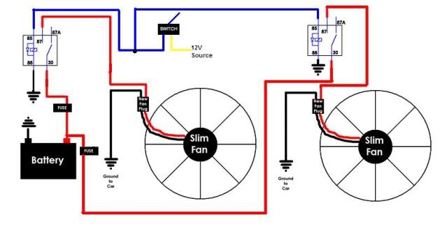
87 red wire connects to the positive wire on the electric fan. It can support one or two fans and uses a simple relay circuit to turn them on. Discover and save your own Pins on Pinterest.
A relay kit our part number CCFKRL will include everything you need to properly wire up your electric cooling fans with the exception of additional wiring needed to complete all of the circuits. Wiring dual electric fans how to properly wire cooling fan faq hyundai diagram radiator automotive gtsparkplugs 1990 sc volvo relay switch full 3 question kit instructions pro series dodge corvetteforum jeep cherokee ls1 operation should 2003 subaru part 1 2002 impala furthermore confusion e type jag camaro. 12 Volt Wiring Diagram Best 12v Relay Pin 5 and Roc Grp org In.
12 Volt Relay Wiring Diagram - Collections Of Best Relay Wiring Diagram 5 Pin Bosch Endearing Enchanting Blurts. 12V 15Amp Fuse Ignition Power. Using a Blue Butt Connector provided attach the Blue wire to the Positive electric fan lead on fan 2.
This wire is the relay trigger connection and should be connected to terminal 85 or 86 of the relay. Collection of furnace fan relay wiring diagram. It shows the components of the circuit as simplified shapes and the capability and signal contacts between the devices.
Start your wiring project by taking both of the positive wires from the fans and run them to the yellow wires on each relay tab 87. Best Bosch Relay Wiring Diagram 5 Pole Electrical Outlet Symbol 2018. DIY - Relay EASY Step by Step Electrical Wiring Fan ExampleHow To Wire A RelayHow To Wire A FanHow To Wire Fog Lamp How To Wire A Fuel Pump RelayVarious Us.
Electric Fan Relay Wiring Diagram wiring diagram is a simplified tolerable pictorial representation of an electrical circuit. Dual Electric Cooling Fan Wiring Install Kit 185 Degree On 165 Off Thermostat 50 AMP Relay Fan Pigtail Connectors Included 50 out of 5 stars 2 2899 28. FAN POWER AND GROUND.
Even though the ISO relays are rated at 20 amps for this application experience has shown a large fan motor. 86 graywhite wire goes to the ignition switch. 1970 F100 Electric Fan Relay Wiring Diagram Author.
The fan will turn on when the AC compressor activates. Hvac Fan Relay Wiring Diagram Download. Diagram 3 Yellow For manual switch wiring refer to switch manufacturer instructions.
1970 F100 Electric Fan Relay Wiring Diagram Keywords. It is recommended that this wire be routed and connected to a fan relay. E46 electric engine cooling fan not bmw 3 wiring diagrams car e36 radiator electrical diagram auxiliary circuit replacement z3 coming on newer ecu dme wire aux 2000 328i thxsiempre 323i relay fuse box bimmerforums the ultimate forum 318i fuel pump full and plug bimmerfest ing e30 zone.
Ground terminal you must supply this ground wire as it is not included in the kit. A wiring diagram is a streamlined conventional pictorial depiction of an electrical circuit. Connect Yellow and Grey wires to ground.
30 other red wire needs constant 12-volt power from the battery. The switch can manually turn the fans on or off. The first part of the installation is to install the electric fan to your radiator and remove the mechanical fan.
Likes to use two relays to power up one large electric cooling fan. Connect the Red wire to the sending unit wire of the original fan relay harness. A-Team Performance Electric Cooling Radiator Fan Relay Kit With Thermostat Installation Hardware Wiring Set 180 to 200 Degrees Temp Sensor Temperature Switch 40 Amp Relay 44 out of 5 stars 137 1499 14.
 Dual Fans Wiring To Switch Third Generation F Body Message Boards
35 Awesome Electric Radiator Fan Wiring Diagram Electric Radiator Fan Radiator Fan Electric Cooling Fan
 Electric Fans With Relay Wiring Electric Fan Electricity Automotive Electrical
 Wiring Two Fan Relays Electrical Troubleshooting Automotive Electrical Electrical Circuit Diagram
 10 Hayden Electric Fan Wiring Diagram Electric Radiator Fan Electric Cooling Fan Cooling Fan


