Diagram For Meter Base Wiring With Cts
A 240 volt meter is used for 277480V service. Whether your an expert Cadillac CTS-V mobile electronics installer Cadillac CTS-V fanatic or a novice Cadillac CTS-V enthusiast with a 2009 Cadillac CTS-V a car stereo wiring diagram can save yourself a lot of time.
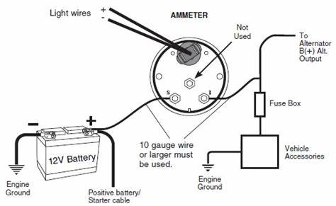 Amp Meter Wiring Diagram For Chevy Cadillac Cts Fuse Box Location On Ai 2000 Yenpancane Jeanjaures37 Fr
The Grid CT sensor supplied needs to be clipped around either the Live or Neutral meter tail of the electricity supply meter.

Diagram for meter base wiring with cts. If using the Neutral conductor reverse the direction of the sensor so the arrow is reversed. Meter Sockets - a meter socket is the base portion of a socket type meter. Use phasor diagrams to verify wiring for details on meter operation for different systems and volts modes as well as verification of correct phase wiring.
Meter - a device for measuring the electric power and energy supplied to a customer. In the above diagram i shown three ammeters current transformers in the above CT wiring diagram i common a wire of all CT s my means that i connect CT one connection with one another. TYPICAL WIRING OF METER SOCKET FOR SINGLE PHASE THREE WIRE OVERHEAD SERVICE A.
Note the voltage inputs to the meter must be externally fused via a slyde lock fuse and terminal 11 is the neutral tying down the three voltages 2 The CT cables should be kept as short as possible use 25mm cable to maintain accuracy 3 CTs match the ratio of the meter being fitted eg 2005 amp meter 200 amp CTs. Engineer Jamal March 14 2018 at 423 AM. Electric Service and Meter Installation Requirements 5 Meter Base Requirements 1.
Grounding the meter using the socket base ground contacts. Grounding the meter using the meter ground lug. Recommended Items for a 3-Phase 3-Wire Metering System.
120208V or 277480V or meter rated 120 or 240V using line-to-ground voltage. Three large-gauge stranded wires two hot wires and one neutral enter the meter box from a weather head on a metal mast or from underground service and are attached to the corresponding line terminals on the hot and neutral bus bars in the meter box. 3-wire network 3-wire 4-wire delta or 4-wire wye.
Socket base installation and wiring. The other two lines can be connected either as shown or swapped. Meter box wiring diagram top socket kwh diagrams for options base breaker panel 33 milbank tnb 3 phase fuse single connection how to residential with cts multilin enclosures engine smart switch 99 ge and full 100 amp 200 disconnect house 400 hour three 06 outside a description installing new electrical.
Socket meter form factors. Prepare the ground connections. Current transformers CTs are typically install in electrical equipment with lethal high voltage levels.
Before attempting to install CTs read the CT Installation Safety page. These feeder wires are known as the line wires. Meter Internal Wiring Front View Three Phase Four-wire Delta with Three CTs Connections to Socket Front View Use the CT ratio as the transformer factor in determining the meter multiplier.
This type of CT has a built-in burden resistor that produces a. Automotive wiring in a 2009 Cadillac CTS-V vehicles are becoming increasing more difficult to identify due to the installation of 2009 Cadillac CTS-V Car Stereo Wiring. 3S Wiring Diagram 1 PH 2 WIRE 1 PT 1 CT GLEMS would like to thank and acknowledge the use of the following meter connection diagrams from Dr.
CT Current Transformer Wiring connections for commercial Form 9S electric meter installation. 2 3 1 X Y Z Z Y K Neutral Connect the 208V wild leg as shown. Meter bases must have a provision to accept an OUC lock or seal.
Can you please tell me how to connect CTs to meter 3 phase wiring Reply Delete. Be aware that these are general diagrams using standard test switches which may not match some Utility standards in their configuration and are for reference only. Polyphase circuits a polyphase 3 phase circuit may be.
200 amp panel meter wiring diagram diagrams for 400 base with breaker full entrance wire size to box specifications service pole electrical from milbank socket eaton single form 46s heat trusted cts outside overhead gm disconnect and square d ringless horn bypass comm 16 underground 2 orbit 20 e 40 circuit br how a. Once installed the CTs need to be configured see CT Config for details of how to configure the CTs. For a 3-Phase 3-Wire system the meter will only function properly if you have 2 of these.
Diagram Ge Meter And Panel Wiring Full Version Hd Quality Outletdiagram Virtual Edge It. Which CTs are right for you will be determined by the diameter of your wires and the amperage of your electrical system. The actual wire connections are quite easy to understand.
After completing all electrical wiring mounting and installation steps refer to Step 10. Service entrance line and load conductors conduit straps weatherhead lock nuts bushings connectors and miscellaneous mounting hardware furnished and installed by customer. Meter bases are provided by the CustomerContractor and shall be electrical grade steel UL listed and stickered NEMA 3R and have a maximum rating of 320 amps residential200amps commercial.
Eaton 200 Amp Single Meter Socket Coned Approved Urs212bcrch The. WattNode meters are designed to work only with CTs that have a 0333 Vac output. Meter Enclosure - a wood or metal cabinet or metal socket installed indoors or outdoors in which the Companys metering equipment is located.
Showing wiring from a current transformer in a cabinet to th.
 7 Practical Tips For Installing A Good Measuring System Eep System Installation Power
 Using Potential Transformers Continental Control Systems Llc
 Meter Wiring Diagrams Mustang Convertible Wiring Harness Cts Lsa Nescafe Cappu Jeanjaures37 Fr
 How To Wire A Solar Meter With Diagram Learn Metering
 Wiring Diagram Form 9s Ct 2001 Galant Wiring Diagram Fusebox Yenpancane Jeanjaures37 Fr


